|
Today I’m going to show a good way to add an instrument handle to a TestStand sequence. I’m using a VISA USB instrument, the Keysight U2001A power sensor. I’ve written about this instrument before. First I’m going to create a little VI that will call the initialization driver of the U2001A power sensor. You can see in Figure 1 that there is a VISA resource name that is specific to this instrument. The issue with this is when this VI is called in TestStand the string has to be saved in the sequence file and it can only ever use that specific instance of the power sensor or else we have to modify the sequence file. 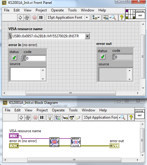 Figure 1. VI with a VISA Resource Name Instrument Handle In TestStand it would look as shown in Figure 2. Either the Device Name is set as a hard-coded string or it is set to default from the VI that contains a hard-coded string. 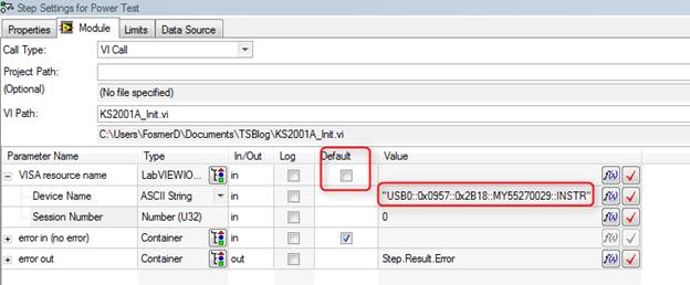 Figure 2. Hard-coding an instrument handle into your sequence can be problematic. A better way to do it is to set an alias for power sensor in NI-MAX and then put that alias into your VI and sequence. Figure 3 shows setting an alias in NI-MAX in the Name field. 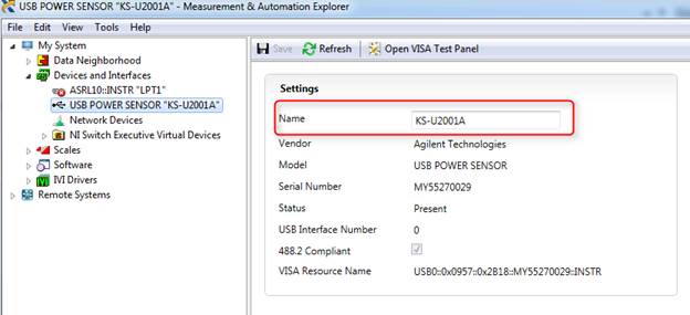 Figure 3. Creating and instrument alias in NI MAX. Now in the sequence file, there is a special variable type just for this purpose called LABVIEWIOControl and the DeviceName property of it is set to the alias of KS-U2001A. The SessionNumber property should stay at zero. This is shown in Figure 4. 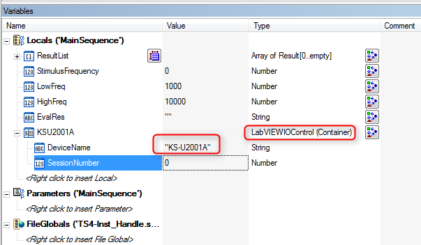 Figure 4. Assigning the instrument alias to a LabVIEWIOControl variable contained in a TestStand sequence. Going down to look at the module adaptor shown in Figure 5, the local variable is set to the new KSU2001A variable. This could also be a good variable to make global, that way you can access this instrument in any sequence or sub-sequence. 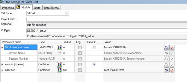 Figure 5. Set the new LabVIEWIOControl variable to the input of the VI in the adapter. (Also, consider making this a global rather than a local) SummaryIn this post I went over how to use NI MAX to create a VISA resource name alias to be used by a sequence file to access and instrument. The advantage of this is you do not have to change the specific VISA name stored in your sequence file to match the specific instance of the instrument connected to the computer running the test sequence. However, you still have to create the same alias in NI MAX for that instrument on any computer that will run the sequence file. Source CodeFind the source code for this post here
0 Comments
In part 2, I talked about preconditions, post actions and some other ways to add limits to tests. In this part I’ll continue looking at some of the other step types, specifically:
Creating a sub-sequenceIf you have ever read anything National Instruments puts out on good code development practices they always talk about coupling and cohesion. That is, making code modules that are loosely coupled and have high cohesion. Coupling means that code modules are for the most part independent and not too “coupled” together. Cohesion means that the all the code in one module is there to perform the one purpose of that module. One way to build cohesion into a TestStand sequence is to make the separate tests (or whatever logical division you are using) into their own sequences. You can either have a sequence file call other sequence files or you can create a subsequence that is called from a main sequence. The difference between the two is that subsequence is not visible in file directory, it’s just stored in the main sequence. Starting with the TSBasics2.seq sequence file from part 2 and renaming it TSBasics3.seq, I’ll show how to turn the Sine Amplitude and Frequency Test into a subsequence. Figure 1 shows the sequences pane, right click and select insert sequence. 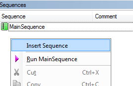 Figure 1. Inserting a sub-sequence in the Sequences pane. Name the new sequence AmplitudeAndFrequencyTest. Cut and paste the steps from the MainSequence into the new AmplitudeAndFrequencyTest sequence. At this point this new sequence is still not called, so we have to drag a sequence call step from the Insertion Palette into the MainSequence and set it to call the new AmplitudeAndFrequencyTest sequence. Rename the sequence call, as shown in Figure 2, right click and select Specify Module. Then, click on the Use Current File check box and select AmplitudeAndFrequencyTest from the drop-down list as shown in Figure 3. 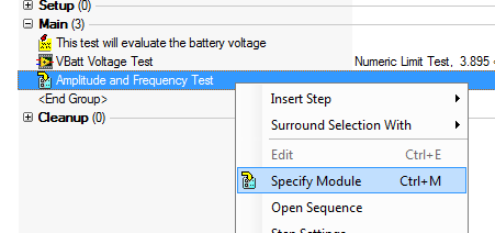 Figure 2. Specify the sequence you want to call with a Sequence Call step type. 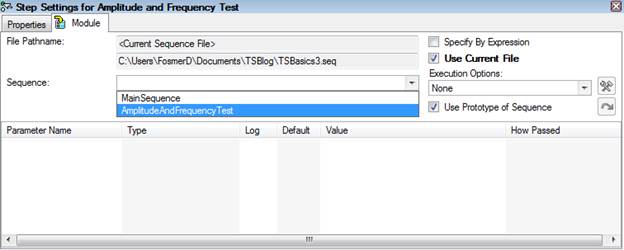 Figure 3. Select the AmplitudeAndFrequencyTest sub-sequence to call. There is one more thing to fix. Since we used local variables in the main sequence to move the amplitude and frequency measurements into the limit steps, we have to put those local variables in the new AmplitudeAndFrequencyTest subsequence. These can just be cut and pasted from the main sequence. Message popup and passing parametersNow that we have a subsequence in order to interact with this subsequence in a way that maintains good cohesion we have to add parameters to the subsequence. First, let’s use the Message Popup step type that will allow the user to set the stimulus frequency. This message popup will set the users input to the local variable called StimulusFrequency. Then we will add a parameter to the AmplitudeAndFrequencyTest subsequence called SetStimulusFrequency which will be passed to the VI for testing and we will see the result on the report. Add the message popup step type (Figure 4) 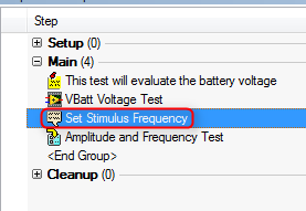 Figure 4. Adding a message popup step type. Create a local variable in the main sequence called StimulusFrequency. On the message popup, rename it to “Set Stimulus Frequency” and go to the Expressions tab of the step properties. Add the Post-Expression, Locals.StimulusFrequency=Val(Step.Result.Response) as shown in Figure 5. This will assign the user response to the local variable and the Val function will convert the string to a number. Go to the Options tab of the Message popup and click the Enable Response Text Box option. This is what allows the user to input a value. 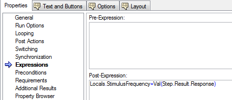 Figure 5. Adding a variable for a response text box type message popup dialog box. The next task is to go into the Amplitude and Frequency Test sub sequence and create a parameter called SetStimulusFrequency shown in Figure 6. This will be how the sub-sequence is passed the stimulus frequency from the upper level main sequence. 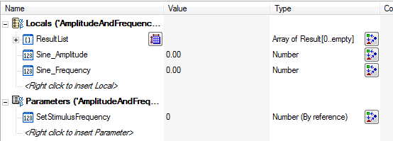 Figure 6. Adding a parameter to allow passing data from the main sequence to the sub-sequence. To add this as a parameter, from the MainSequence we click on the Amplitude and Frequency Test sub-sequence. Select the SetStimulusFrequency parameter and use the Value field to set the value that will be passed to it. Here we are using the local variable StimulusFrequency. See Figure 7. 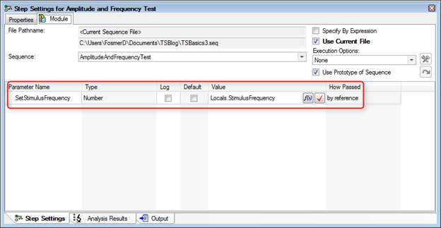 Figure 7. Setting up the local variable that will be used as the parameter to pass into the sub-sequence. Another thing we should do when adding user input is validate that input. The user input is accepting a string and we are converting it into a number, we should make sure that is a valid number. Right now the limit on frequency is 4999 to 5001, let’s open that up to 1000 to 10000. I’ll make two locals holding these values, 1000 and 10000. Then I’ll add a status expression to make sure the entered value is within this range. Figure 8 shows the expression. If the input is not in this range, then the step fails and we’ll add a post action to repeat the step on failure shown in Figure 9. 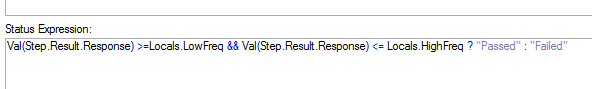 Figure 8. Expression to check if the user input is within the acceptable bounds. 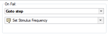 Figure 9. In the event of an invalid input the dialog will popup again to ask the user for input. We also have to go the Run Options tab in Figure 10 and uncheck the Step Failure Causes Sequence Failure option, or any incorrect entry will cause the test to fail. Now, if you enter a number smaller or larger than 1000 to 10000, it will just pop back up to reenter. This isn’t totally fool-proof, for one thing there is no dialog explaining that you entered an invalid value and you could probably enter text into the dialog that would convert to a number in this range and the sequence would pass with some random input. Another problem is the validation values are not tied to the actual limits, so there could be a mismatch. So… room for improvement. 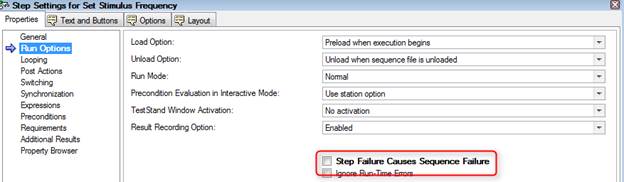 Figure 10. Uncheck the option that step failure causes sequence failure. Failure here indicates incorrect input not test failure. This last step also gave us a chance to write some expressions. Expressions are very powerful, but I’ve found they can be tricky and the help isn’t always easy to find. The expression browser shown in Figure 11 is probably the best bet and a lot of experimenting and learning has to take place. 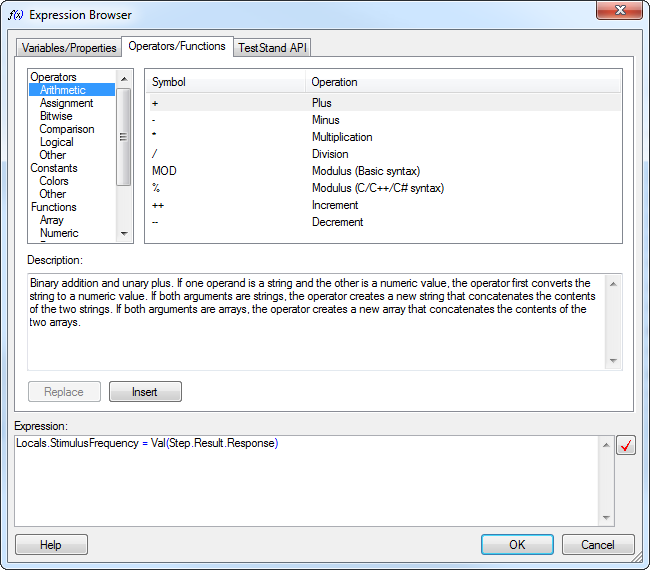 Figure 11. Expressions can be extremely complex, the Expression Browser provides help and context to writing them. Using the Property Loader The last thing I’m going to look at today is the Property Loader. The Property Loader is a step type that will load properties from a file or database. This is super-useful because you can keep things like your test limits in a separate file and change them without having to change the sequence file itself. It’s pretty easy to set this up, I’ll demonstrate with loading properties from Excel. First drag a Property Loader step type into the Setup step group of the main sequence. This is the perfect type of operation to put into the Setup step group of the as it fits well into the logical category of setup. Since we already have all are limits setup in the sequence file and sub-sequence it’s easy to create the limits Excel file. Click on Tools -> Import/Export Properties… On the Source / Destination tab select file and Excel, on the Properties tab select all sequences and click the limits button. Click Export, give it a file name and click done. See Figure 12 and 13. 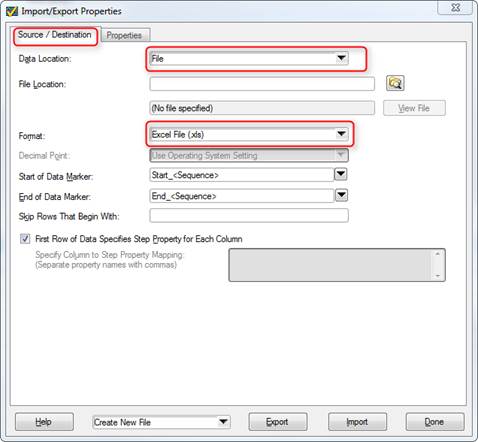 Figure 12. Set the file type to Excel for the Property Export operation. 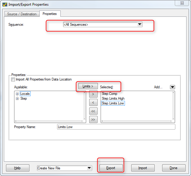 Figure 13. Selecting limits as properties to be exported to an external property loader file. Now let’s take a look at the file that was created in Figure 14. You can see that the limits we previously setup are in there along with empty fields for locals, file globals, and station globals. 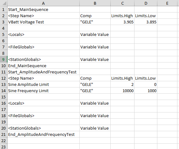 Figure 14. Excel file result of the property loader export function. Going back to the main sequence, click on the Property Loader step we added and click Edit Property Loader… in the step settings. Make the settings shown in Figure 15 for the Properties tab and shown in Figure 16 for the Source tab (navigate to your property file you created as your file path will be different). 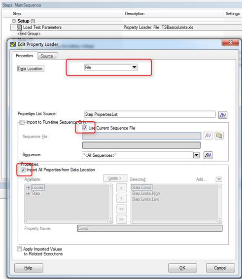 Figure 15. Property loader step type settings. 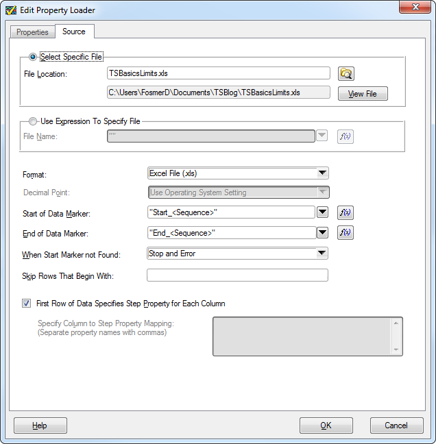 Figure 16. Property loader step settings for data source. Next thing I added, that is optional, is a message popup to the AmplitudeAndFrequencyTest sequence to show the limits that were read from the limits file. Figure 17 shows the expression needed to create this popup message. This is just to illustrate that the limits are being pulled from the file at this point and not what is saved in the sequence file. We don’t have to do anything to the sequence file to get the limits applied to the test results, that’s all handled in the property loader. One thing we may want to do is simply zero out the limits in the sequence file so no one is tricked that the limits are stored there. This may call for a Label comment as well. The bad thing about zeroing the limits is now when you read the sequence file the descriptions would just list limits of zero. So, it’s up to you what you like. 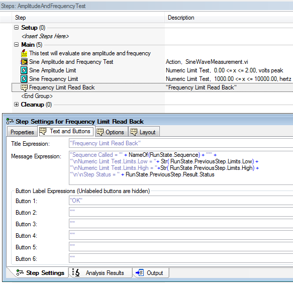 Figure 17. Expression that reads back the frequency limits as loaded with the property loader file. SummaryThat’s all I’m going to go over in this post. I worked through adding a sub-sequence with a parameter, a message popup and wrote some statements to validate the input. I also showed the basics of using the Property Loader to load limits and other values from an external file. Source CodeFind the code for this post here RelatedIn Part 1 on TestStand I programmed the very minimum to get a test system going. In this part, I’ll add some more steps and show a lot of other useful features. This will mostly involve test steps and flow control. Using A PreconditionThe first thing I did was add a new test VI, a battery voltage test. Note again that this isn’t a real measurement, but for this one I added a little randomization so the results are somewhat more of a realistic simulation. Figure 1 shows the battery voltage test VI. 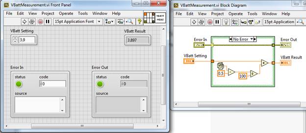 Figure 1. VI to simulate a battery voltage test. I have added this new test to my sequence file before the sinewave test, this time I used the Numeric Limit Test adaptor as this VI has only one output that I want to apply a limit. You can see from the code above that the maximum range the simulated VBatt Result can be is 3.895 to 3.905, so that is what I set the limits to. It’s slightly easier to setup the Numeric Limit Test than it is to setup the Multiple Limit Numeric Test. First I go to the Limits tab of the Step Settings to enter the high and low limit as shown in Figure 2. Next I went to the Module tab and set the VBatt Result Value expression to be Step.Result.Numeric. This is shown in Figure 3. This again is using TestStands built-in results collection. That it, then the Data Source tab is automatically set to Step.Result.Numeric as well. 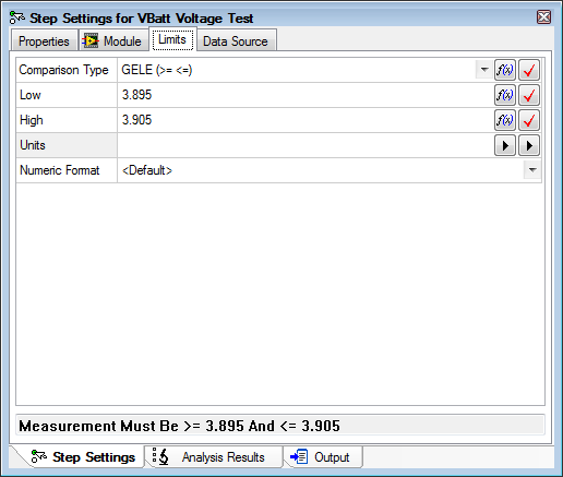 Figure 2. Setting high and low limits for the battery voltage test. 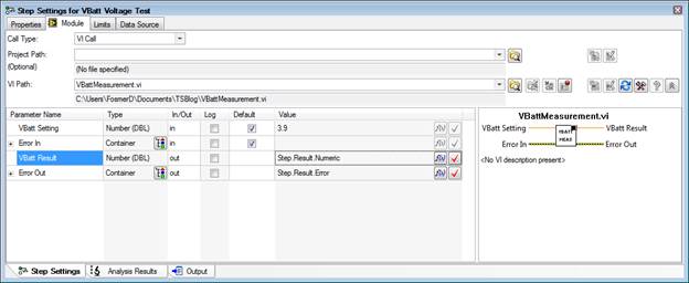 Figure 3. Linking the battery voltage VI result to the TestStand results collection. The next thing I’m going to do is apply a precondition to the sine amplitude and frequency test. A precondition is an expression that is evaluated before a step executes. I’m going to create a precondition that says the Sine Amplitude and Frequency Test will only execute if the VBatt Voltage Test passes. Since this is such a common task there is a very quick way to write this expression. Go the Sine Amplitude and Frequency step and go to the Properties tab of the step settings. Click on Preconditions and click the Precondition Builder icon shown in Figure 4. 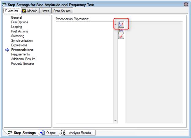 Figure 4. Location of the Precondition Builder icon. In the Precondition Builder dialog box click the VBatt Voltage Test step, then click Insert Step Pass button and that’s it. This is shown in Figure 5. 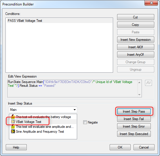 Figure 5. Setting a precondition that the VBatt Voltage Test pass for the Sine Amplitude and Frequency Test to be run. Save the sequence file and in the Execute pull down menu click Single Pass. The sequence will run and you can see from the report that both the VBatt Voltage and Sine Amplitude and Frequency Tests pass. To test the precondition we can force the VBatt Voltage Test to fail. Right click on the VBatt Voltage Test step and click Run Mode -> Force to Fail. You can now see in Figure 6 the settings for that step it is set to Force Fail. Run Single pass again and we can see the Sine Amplitude and Frequency Test is never run and set to a status of skipped. Figure 7. 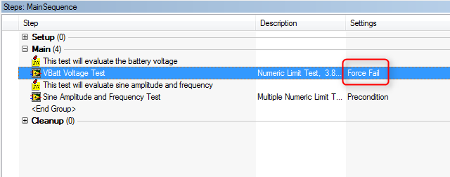 Figure 6. Set the VBatt Voltage Test to Force Fail in order to test the Sine Amplitude and Frequency Test precondition. 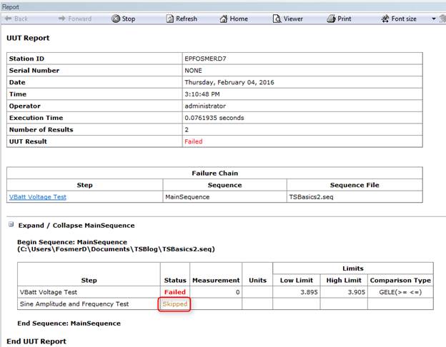 Figure 7. The test reports shows that the Sine Amplitude and Frequency Test was skipped due to failing the precondition. Using a Post Action instead of a PreconditionThere are lots of ways to do things in TestStand. For example, I’ve worked with some engineers who don’t like to use preconditions because they feel it hides test flow inside the test step where you can’t see it. A way you can avoid preconditions that also saves quite a bit of work is to just program the conditional step to go to cleanup on fail. Say there were 4 other tests along with the Sine Amplitude and Frequency test and we don’t want any of them to execute if the VBatt Voltage Test fails, we can just tell the sequence to go to the cleanup step on failure of the VBatt Voltage Test and we can skip all the preconditions. Here under the Post Actions property you can see in Figure 8 we’ve left the behavior for on pass to default as go to the next step, but changed the on fail to go to step cleanup. 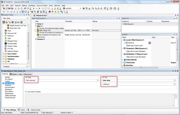 Figure 8. Setting up a post action to go to clean up on step fail. Making limits their own stepAnother method to set test limits is to make them their own test step. This can be nice because if you have multiple limits in one sequence step they are hidden away and not easily view without opening the step. Putting each limit as its own step makes it a little easier to read the sequence. This will also demonstrate the concept of using a variable, which we have not talked about yet. Here is the process to move the Sine Amplitude and Frequency Test limits to their own sequence steps:
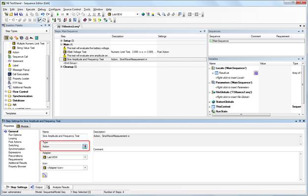 Figure 9. Changing the type for the Sine Amplitude and Frequency test to an Action rather than a numeric limit test. 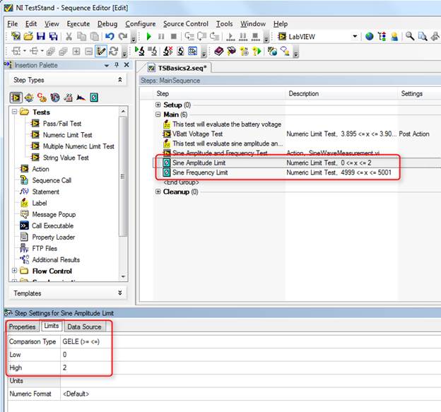 Figure 10. Adding two Numeric Limit Tests for amplitude and frequency with the adapter changed to none. 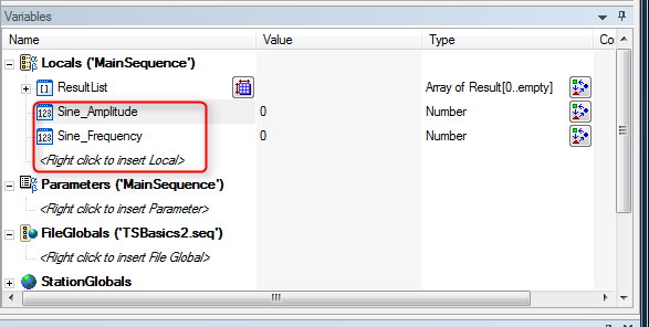 Figure 11. Add local variables as a way to store the amplitude and frequency measurements. 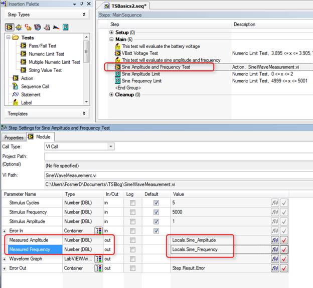 Figure 12. Connecting the output of the Amplitude and Frequency measurement VI to the local variables. 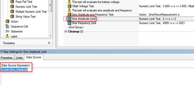 Figure 13. In the limit evaluation steps - set the data source to the local variables. Now if we run the sequence you can see in Figure 14 that it still passes. 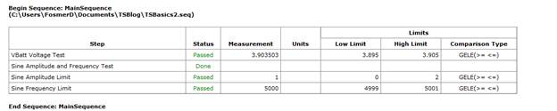 Figure 14. The test report shows the amplitude and frequency evaluation is now in the new sequence steps Improving the format of the test reportOne thing I noticed in the report is all those digits in the VBatt Voltage Test and the Sine Amplitude and Frequency are not in the correct format. If I go to Configure -> Results Processing I can change the way numbers are reported on the report. Figure 15. 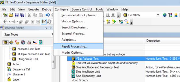 Figure 15. Open the Results Processing dialog box. In the results processing dialog if I click on options then I can edit the number of digits on the report as shown in Figure 16. The default number of digits is 13. 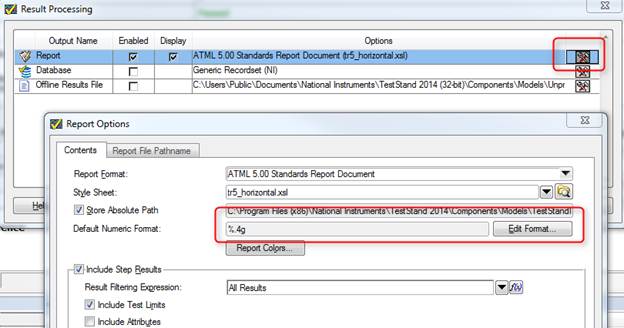 Figure 16. Changing the number of digits shown on the test report. I also noticed that the limits on amplitude and frequency should have some digits. Go into the limit step and add a custom numeric format. I also added a unit of measure, which makes it look a little better, see Figure 17. 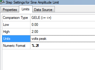 Figure 17. Setting the number of digits that are displayed on a limit. We also need to go update the local variables to keep them from cutting off any digits. Right click on the amplitude and frequency variables and change them to Real with two digits of precision. Figure 18 shows the Numeric Format dialog box. 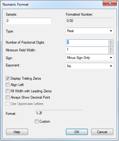 Figure 18. Adjusting the numeric format of a variable. I also went back and added a unit for the VBatt test. Now in Figure 19 our report is looking a little bit better. 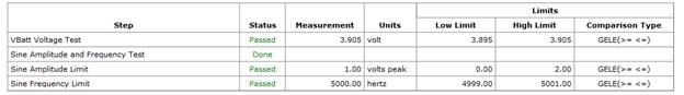 Figure 19. Updated test report after adjustments for number formatting and adding units. SummaryIn this post I showed some different methods to control the flow of the test with preconditions and post actions. I also showed how to use local variables rather than the automatic results built into TestStand to apply limits to tests. Finally, I showed a couple little things to format the test report. Source CodeFind the code for this post here RelatedIntroductionOver the last year or so I’ve been working with NI TestStand quite a bit. While, I’ve worked with LabVIEW for several years, I have not had much exposure to TestStand. I’m hoping to write a blog series on TestStand to aid in my learning. When I started using TestStand my first question was, “how do I use this to make the creation of a test system faster?” I wanted to use LabVIEW and get a test system up and running quickly but I didn’t have any test executive infrastructure in place. That is I just wanted the operator interface, test sequencer, and report generation done so I could focus on tests. Well, that’s what TestStand is supposed to do and I was going to figure out how to make it do it. Unfortunately, I didn’t know much about TestStand and I had to figure out how to do all the basic stuff. NI always has lots of training materials available, but I just wanted to know how to get something super simple going, and I couldn’t quite find the help I wanted. If you start with an empty sequence file it looks like Figure 1. 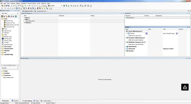 Figure 1. Empty TestStand sequence Navigating the TestStand Sequence EditorOn the left is the Insertion Palette, note in Figure 2 I’ve pointed out the Module Adaptor selection area. I have mine set to LabVIEW as I want to call my labview code on each test step. Other choices are C/C++ dll or .NET. Simply click on these to change the adaptor. There’s lots of other useful stuff in the Insertion Palette I’ll talk about later. 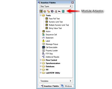 Figure 2. Module Adaptors on the Insertion Palette Another area of interest is the Steps Pane. That’s right in the middle and controls your test steps and test flow. Figure 3 shows the Steps Pane. I think the Steps Pane is technically held in the Sequence File Window. I don’t know, these terms aren’t that important. 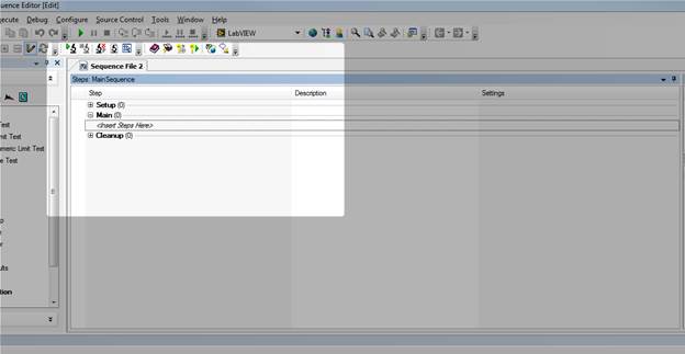 Figure 3. Steps Pane of the Sequence Editor. Off to the right is the Sequence Pane and the Variables Pane. Figure 4 shows the variables pane. 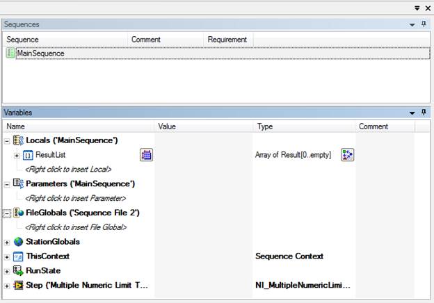 Figure 4. Variables Pane of the Sequence Editor. You’ll see that dealing with all these panes and windows can get to be a pain (I’m so funny). There are a lot of ways to move and dock all these windows. You can even pull some of them out of the sequence editor onto the Windows desktop on another monitor. So play around with it. Using a Test AdaptorNow let’s say we have some LabVIEW code and we want to run it in TestStand. Based on the code, we will pick one of the standard LabVIEW test adaptors. In this case I’ll chose Multiple Numeric Limit Test since my VI has multiple outputs that I want to evaluate with a limit and it’s probably the most useful one. In Figure 5 I dragged the Multiple Numeric Limit Test from the Insertion Palette to the Steps Pane under the Main section. 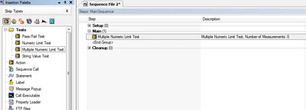 Figure 5. Use of the Multiple Numeric Limit Test adapter. Clicking on the new Multiple Numeric Limit Test, we can see in Figure 6 that the Step Setting pane is now populated with several tabs and settings options. I’m going to click on the Module tab and browse for the VI I want to run. 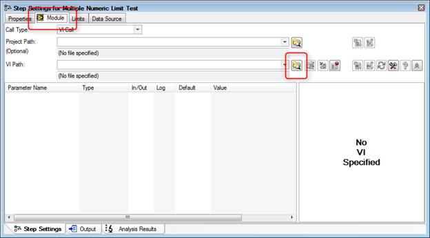 Figure 6. Selecting a module for the Multiple Numeric Limit Test adapter. The VI I am loading is just a simple sinewave generator I wrote up quick in LabVIEW. Its outputs are the sinewave amplitude and frequency. I’m going to pretend that this is my test data. See Figure 7. 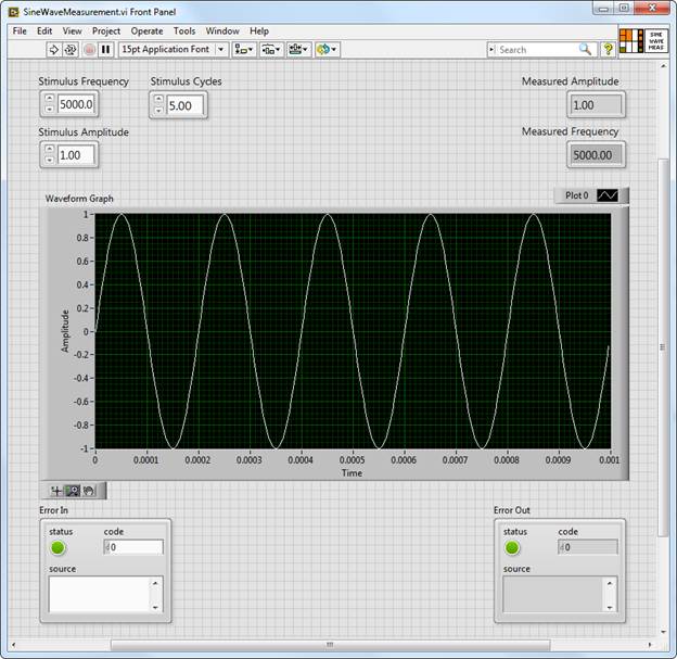 Figure 7. Front panel of sine wave measurement VI that will be used in the sequence. Now that the VI is loaded into the test sequence let’s setup TestStand to run the VI and apply limits to the measurement results. There are multiple ways to do this, the first way I know is to use the built-in results collection of TestStand. Start on the Limits tab shown in Figure 8, and use the plus sign to add two measurements. Change their names to “Amplitude” and “Frequency” or whatever makes sense. 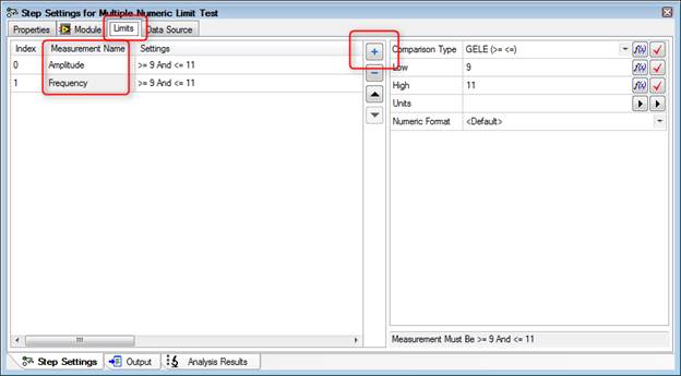 Figure 8. Applying limits to the amplitude and frequency outputs of the test VI. Next go to the Module tab shown in Figure 9 and click on the Expression Browser button in the Measured Amplitude parameter row. 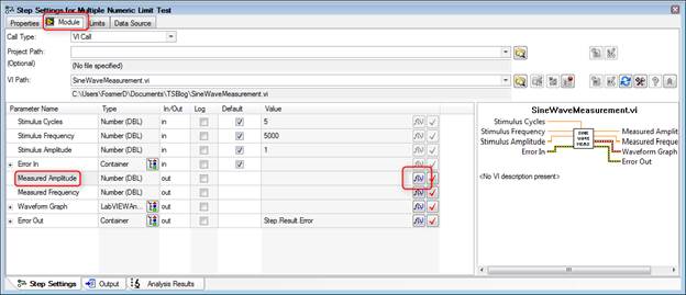 Figure 9. Accessing the Expression Browser for the amplitude output of the test VI. Once you click on the Expression Browser button you’ll see the Expression Browser dialog box shown in Figure 10. What we are trying to do is map the output of our VI to the result collection measurement name we created when we added the amplitude and frequency limits. Browse into Step -> Result -> Measurement -> [“Amplitude”] ([0]) -> Data and then click on Insert and OK. 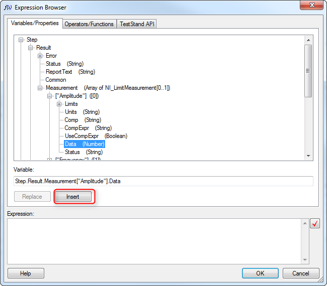 Figure 10. Connect the amplitude output from the test VI to the sequence file to be used in the limit evaluation. Go to the Data Source tab as shown in Figure 11 and click the check box called Specify Data Source for Each Measurement. Under Data Source there are two lines one for the amplitude and one for the frequency measurement. Here we are connecting our data from the TestStand results collection to the limits to be evaluated. Figure 12 shows how to use the expression browser to create the statements shown in Figure 11. 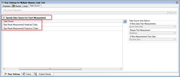 Figure 11. Connect the data source to the test step to be evaluated as limits. 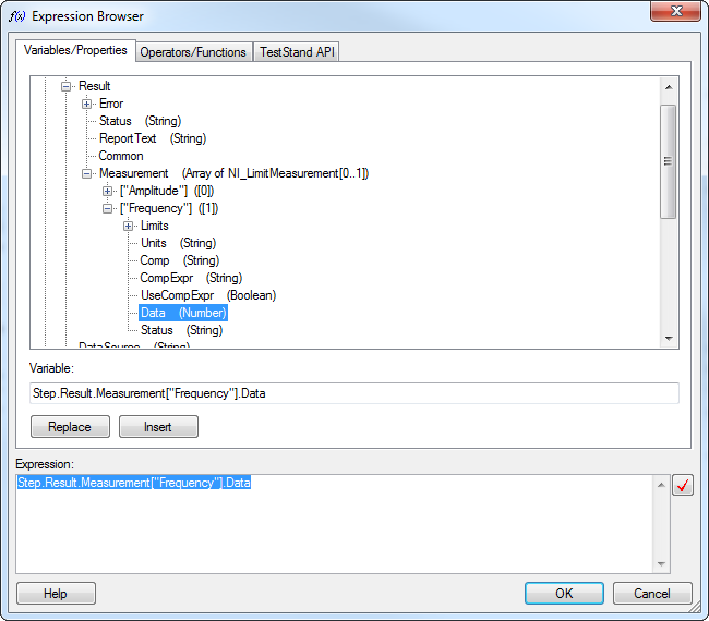 Figure 12. Using the Expression Browser to create the data source statements. Now go back to the Limits tab shown in Figure 13 and set the limit span. In my VI, the default amplitude is 1 and the frequency is 5000. As you can see there are several options for one or two sided limits, inclusive and so on. I chose GELE and selected the units. 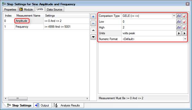 Figure 13. Options to set the limits amplitude limits, comparison type, low, high, units and numeric format. Returning to the Steps Pane, name the step something like “Sine Amplitude and Frequency.” Also, drag a label from the Insertion Palette as a way of documenting this step. The Label step type is shown in Figure 14. 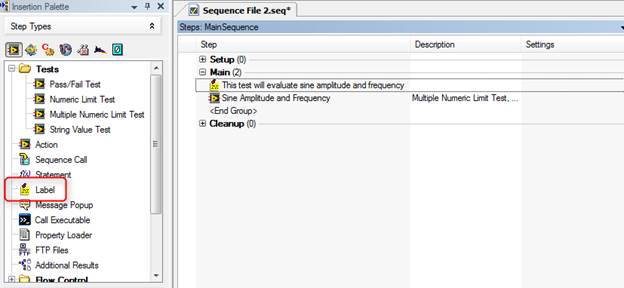 Execute the SequenceWe are actually pretty close to a complete test system at this point. It might not test much but we can now enter a DUT serial number, execute the sequence and get a report. In the Sequence Editor, click Execute-> Test UUTs, the UUT Information dialog box in Figure 15 will appear to enter a serial number for the part. Also, if you have a UBS bar-code scanner attached to the system it will automatically accept the input into this dialog box field. I didn’t know this, but a USB bar-code scanner will read text into most software, it’s just like a keyboard or mouse. You can even scan right into Excel. 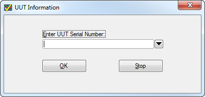 Figure 15. The UUT Information dialog box built into TestStand Type something in there like “1234” and click OK. TestStand will execute will show that the test sequence passed. The little dialog box that pops up that says “Test Sequence Passed” is shown in Figure 16, this dialog is controlled and created by the process model (so is the UUT Information, for that matter). 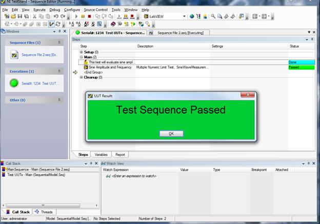 Figure 16. UUT Result dialog box shown after test run pass. Click OK on the UUT Result dialog and click Stop on the UUT Information dialog box. The test report will pop-up and you can see all the information and measurements that are collected. It’s a pretty good report right out of the box. Figure 17 shows an example of the report. 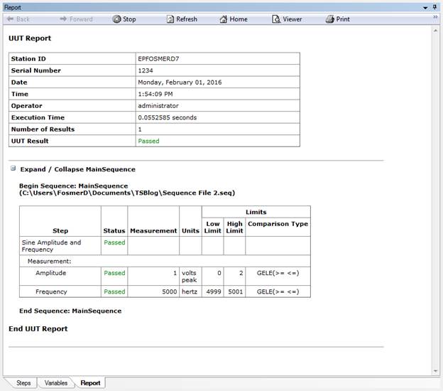 Figure 17. Example of the default sequence report created by TestStand Each time the test is executed the report will be saved in xml format to the directory in which your sequence file is saved. One last step to creating a fully functional test system is adding a user interface. The TestStand sequence editor allows you to run the sequence and your test, but it’s not setup to do real testing by a test operator. TestStand comes with premade test system user interfaces to solve just this problem. Before we look at the user interface we have to create a user with limited permissions to be our operator. In the sequence editor click View -> User Manager. Under the Users section right click and add a user called TestOperator. Right click this new user and select Properties, and click Operator. See Figure 18. 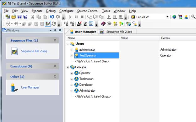 Figure 18. Creating a Test operator user profile in the TestStand user manager. Save the new user setting and close the User Manager. Note that the User Manager changes are a station setting and live with the installation of TestStand on the computer you are using, and are not saved into the sequence file. Go to this path C:\Users\Public\Documents\National Instruments\TestStand 2014 (32-bit)\UserInterfaces and you will find two folders, Simple and Full Featured. In these folders you’ll find the premade user interfaces in a variety of languages. If we go in Full Featured and LabVIEW you’ll find a file called “TestStand 2014 (32-bit) LabVIEW UI – Operator” this is the LabVIEW implementation of the user interface. From this interface you can then load your test sequence file and run it in a production environment. As shown in Figure 19, open the file and login as the new user TestOperator, then open the sequence file that we built and you are ready to test by clicking the Test UUTs button shown in Figure 20. 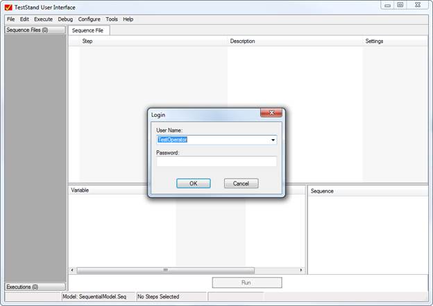 Figure 19. The TestOperator login in now available. 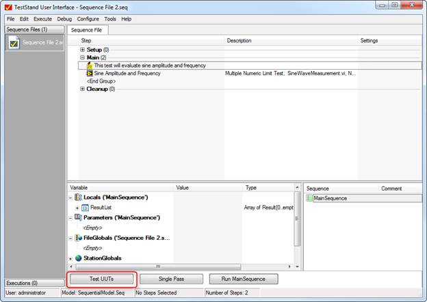 Figure 20. Begin testing by pressing the Test UUTs button. SummaryTestStand is a great tool to building a simple test system quickly as it handles a lot of the infrastructure for you like, user interface and reporting. This was the super basic stuff to load a LabVIEW VI and run it in the TestStand sequencer. TestStand can sort-of be as sophisticated and complex as you want it to be as you become more of a power user. I’m still a beginner, but I will keep writing as I learn and hopefully it will be a benefit to some others and I’ll remember how to do stuff the next time. Related |
Archives
December 2022
Categories
All

|
 RSS Feed