|
In Part 1 on TestStand I programmed the very minimum to get a test system going. In this part, I’ll add some more steps and show a lot of other useful features. This will mostly involve test steps and flow control. Using A PreconditionThe first thing I did was add a new test VI, a battery voltage test. Note again that this isn’t a real measurement, but for this one I added a little randomization so the results are somewhat more of a realistic simulation. Figure 1 shows the battery voltage test VI. 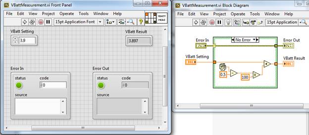 Figure 1. VI to simulate a battery voltage test. I have added this new test to my sequence file before the sinewave test, this time I used the Numeric Limit Test adaptor as this VI has only one output that I want to apply a limit. You can see from the code above that the maximum range the simulated VBatt Result can be is 3.895 to 3.905, so that is what I set the limits to. It’s slightly easier to setup the Numeric Limit Test than it is to setup the Multiple Limit Numeric Test. First I go to the Limits tab of the Step Settings to enter the high and low limit as shown in Figure 2. Next I went to the Module tab and set the VBatt Result Value expression to be Step.Result.Numeric. This is shown in Figure 3. This again is using TestStands built-in results collection. That it, then the Data Source tab is automatically set to Step.Result.Numeric as well. 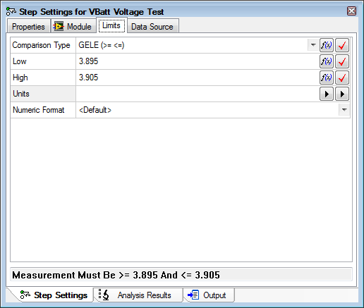 Figure 2. Setting high and low limits for the battery voltage test. 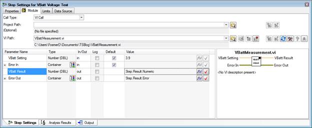 Figure 3. Linking the battery voltage VI result to the TestStand results collection. The next thing I’m going to do is apply a precondition to the sine amplitude and frequency test. A precondition is an expression that is evaluated before a step executes. I’m going to create a precondition that says the Sine Amplitude and Frequency Test will only execute if the VBatt Voltage Test passes. Since this is such a common task there is a very quick way to write this expression. Go the Sine Amplitude and Frequency step and go to the Properties tab of the step settings. Click on Preconditions and click the Precondition Builder icon shown in Figure 4. 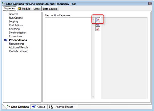 Figure 4. Location of the Precondition Builder icon. In the Precondition Builder dialog box click the VBatt Voltage Test step, then click Insert Step Pass button and that’s it. This is shown in Figure 5. 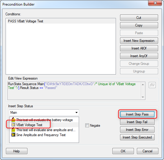 Figure 5. Setting a precondition that the VBatt Voltage Test pass for the Sine Amplitude and Frequency Test to be run. Save the sequence file and in the Execute pull down menu click Single Pass. The sequence will run and you can see from the report that both the VBatt Voltage and Sine Amplitude and Frequency Tests pass. To test the precondition we can force the VBatt Voltage Test to fail. Right click on the VBatt Voltage Test step and click Run Mode -> Force to Fail. You can now see in Figure 6 the settings for that step it is set to Force Fail. Run Single pass again and we can see the Sine Amplitude and Frequency Test is never run and set to a status of skipped. Figure 7. 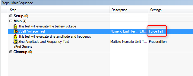 Figure 6. Set the VBatt Voltage Test to Force Fail in order to test the Sine Amplitude and Frequency Test precondition. 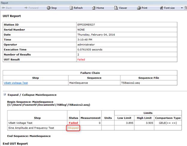 Figure 7. The test reports shows that the Sine Amplitude and Frequency Test was skipped due to failing the precondition. Using a Post Action instead of a PreconditionThere are lots of ways to do things in TestStand. For example, I’ve worked with some engineers who don’t like to use preconditions because they feel it hides test flow inside the test step where you can’t see it. A way you can avoid preconditions that also saves quite a bit of work is to just program the conditional step to go to cleanup on fail. Say there were 4 other tests along with the Sine Amplitude and Frequency test and we don’t want any of them to execute if the VBatt Voltage Test fails, we can just tell the sequence to go to the cleanup step on failure of the VBatt Voltage Test and we can skip all the preconditions. Here under the Post Actions property you can see in Figure 8 we’ve left the behavior for on pass to default as go to the next step, but changed the on fail to go to step cleanup. 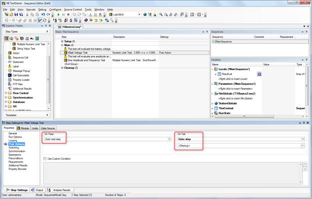 Figure 8. Setting up a post action to go to clean up on step fail. Making limits their own stepAnother method to set test limits is to make them their own test step. This can be nice because if you have multiple limits in one sequence step they are hidden away and not easily view without opening the step. Putting each limit as its own step makes it a little easier to read the sequence. This will also demonstrate the concept of using a variable, which we have not talked about yet. Here is the process to move the Sine Amplitude and Frequency Test limits to their own sequence steps:
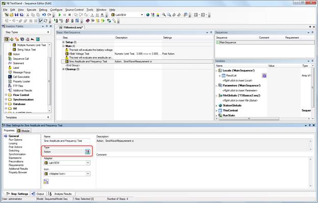 Figure 9. Changing the type for the Sine Amplitude and Frequency test to an Action rather than a numeric limit test. 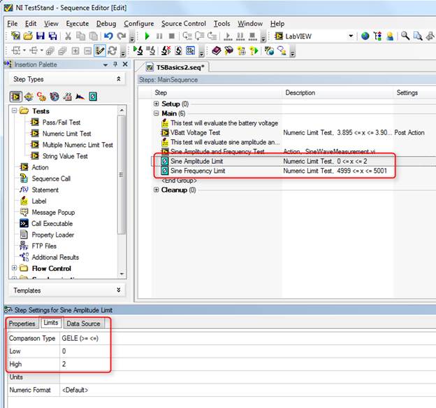 Figure 10. Adding two Numeric Limit Tests for amplitude and frequency with the adapter changed to none. 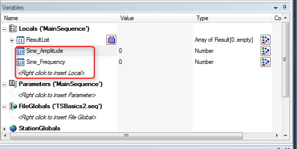 Figure 11. Add local variables as a way to store the amplitude and frequency measurements. 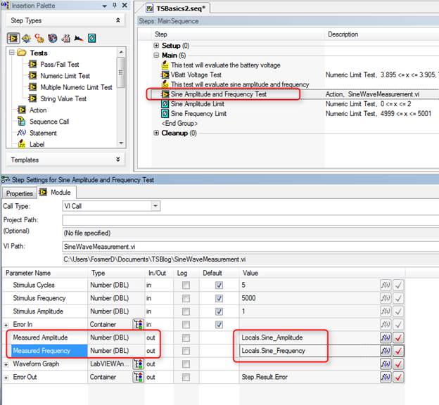 Figure 12. Connecting the output of the Amplitude and Frequency measurement VI to the local variables. 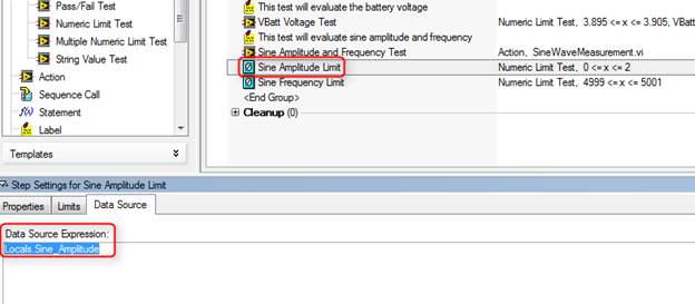 Figure 13. In the limit evaluation steps - set the data source to the local variables. Now if we run the sequence you can see in Figure 14 that it still passes. 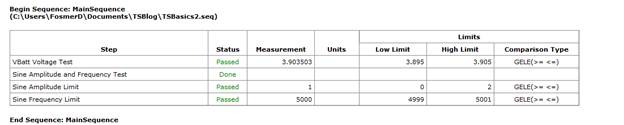 Figure 14. The test report shows the amplitude and frequency evaluation is now in the new sequence steps Improving the format of the test reportOne thing I noticed in the report is all those digits in the VBatt Voltage Test and the Sine Amplitude and Frequency are not in the correct format. If I go to Configure -> Results Processing I can change the way numbers are reported on the report. Figure 15. 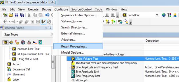 Figure 15. Open the Results Processing dialog box. In the results processing dialog if I click on options then I can edit the number of digits on the report as shown in Figure 16. The default number of digits is 13. 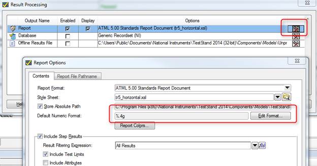 Figure 16. Changing the number of digits shown on the test report. I also noticed that the limits on amplitude and frequency should have some digits. Go into the limit step and add a custom numeric format. I also added a unit of measure, which makes it look a little better, see Figure 17. 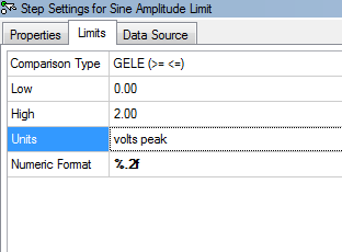 Figure 17. Setting the number of digits that are displayed on a limit. We also need to go update the local variables to keep them from cutting off any digits. Right click on the amplitude and frequency variables and change them to Real with two digits of precision. Figure 18 shows the Numeric Format dialog box. 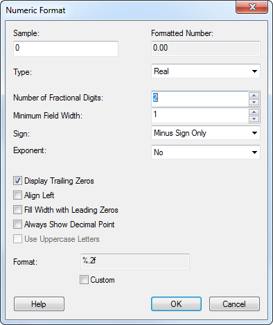 Figure 18. Adjusting the numeric format of a variable. I also went back and added a unit for the VBatt test. Now in Figure 19 our report is looking a little bit better. 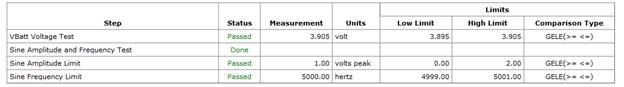 Figure 19. Updated test report after adjustments for number formatting and adding units. SummaryIn this post I showed some different methods to control the flow of the test with preconditions and post actions. I also showed how to use local variables rather than the automatic results built into TestStand to apply limits to tests. Finally, I showed a couple little things to format the test report. Source CodeFind the code for this post here Related
2 Comments
Jay
8/10/2018 03:13:02 am
Nice job. One small feature request. At end of each article, please provide links to prev and next articles (e.g. part1, part3). Thx.
diego
10/8/2022 04:54:05 pm
Hi I just.... It is so cool!! I'm super new in LabVIEW and pxi. I'm looking to perform test in circuit to for example 74hc00 (ic logic gates ) . Can do you give me a way to begin? Your comment will be posted after it is approved.
Leave a Reply. |
Archives
December 2022
Categories
All

|
 RSS Feed