|
I have previously written about how to do some basic things with the PXI instruments I have been working with lately. While I covered using the DAQ to generate and acquire analog signals, I would like to expand on what I wrote there. The NI PXIe 6259 M-series DAQ has three kinds of pins, or physical channels, as NI calls them. There are analog I/O, digital I/O and counter pins. The pins are setup like this. 32 analog inputs (ai0…ai31) 4 analog outputs (ao0…ao3) 64 digital pins (Port 0/line 0 to 31, Port 1/line 0 to 7, Port 2/line 0 to 7) where all of these pins are on Dev1. Dev1 is the DAQ, so if you added another DAQ to the PXI chassis it would be Dev2. Port 1 and 2 are arranged like this 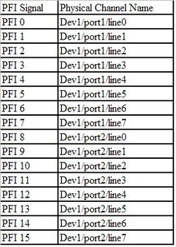 2 counters arranged like this 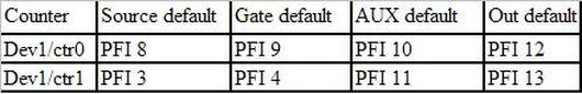 There is also PFI 14 which is FREQ OUT, used as a simple output only frequency generator. PFI stands for “Programmable Function Interface,” which is just a designator they gave it to mean it does something. There is some overlap between the digital pins and the counters. For example, PFI 4 is a dedicated digital pin used for ctr1 gate on counter 1. Digital I/O Example code written to demonstrate digital I/O of the DAQ is shown in Figure 1. The code uses the DAQmx driver to configure a digital input, output and clock signal. The output generates a sequence of digital values and reads them back in on the input when looped back through the matrix PXI card. Counter 0 is configured to be a clock signal where the frequency, duty cycle, initial delay and idle state of the clock are configurable. The digital input is setup to trigger off the clock signal and start acquiring data. The digital output is also setup to trigger off the clock and start generating the programmed data pattern. Notice that the digital output is set to update on the rising edge and the input on the falling edge. This will allow the output level to stabilize before it is read by the input. The clock, digital in and out are all configured to operate with a finite number of samples, 16 used here. It’s a little confusing, but in this case number of samples means clock pulses. Each of the clock, digital input and output are configured with their own task. The input and output tasks are started immediately after the channel is configured, in effect arming the channel as it does not really start until the trigger clock signal is received. Finally, the clock from the counter task is started. This starts the clock sequence and the code waits until the clock is finished allowing all of the digital data to be output and acquired. If I somewhat understand the NI terminology, a channel is created and controlled with a task. For example, you create a digital output channel and then any other code after that related to the channel has to be wired up to the use the same task where the task was created. You can also give the tasks meaningful names to help organize the code. It was a little confusing at first but become pretty intuitive quickly. I guess it’s like the instrument VISA session handles that some older NI drivers used, but you can use multiple tasks within the same instrument.  Figure 1. Digital pattern example block diagram Figure 2 shows the front panel of the code. 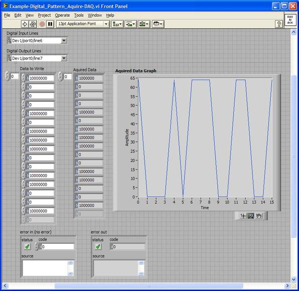 Figure 2. Digital pattern example front panel. In Figure 2 notice that the output and input are configured with only one line, where line 6 is the input and line 7 is the output. These are just arbitrary choices. What is significant is looking at the “Data to Write” array control, in order to set a value of 1 on the output line 7, I need to put a 1 in the 7th bit position (LSB on the right). “Data to Write” is formatted in binary to show this but really the driver accepts a U32 that covers the whole port. The same is true for a 0 value, Labview formats 00000000 as just 0 so it looks a little different than the 1. Also notice, the input line is line 6 so now the bit has moved a position in the “Acquired Data” indicator. You can also see on the graph that the Y axis is in decimal so a high value shows up as a 64. This would probably be a good place to create a new driver where if you are programming a single line only, you don’t have to keep track of the bit position. It’s pretty interesting because there are a lot of possibilities of how you can use this. With some pre-processing you could send a bit stream into a single line (basically, what is happening here) or you can program the whole port at once by just creating a channel as Dev1/port0 rather than Dev1/port0/line7. As also shown, you can split up the port so some of it is configured as input and some as output. Counter The digital I/O example made use of the counter as a clock to synchronize and trigger. The counter can also perform the operations typically associated with a counter, like measuring frequency, period and counting edges. Figure 3 shows the block diagram of an example using the counter to measure frequency. 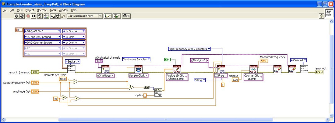 Figure 3 Block diagram measure frequency using DAQ counter The code is very simple. An analog output is connected to a counter input through the matrix. The analog output is configured to generate a sine wave and the counter is configured to measure the frequency. Notice that the programmed sine wave frequency is used to create a max and min value, plus/minus 10, of the measured frequency. This is wired into the counter configuration for accuracy. Figure 4 shows the front panel of the same code. 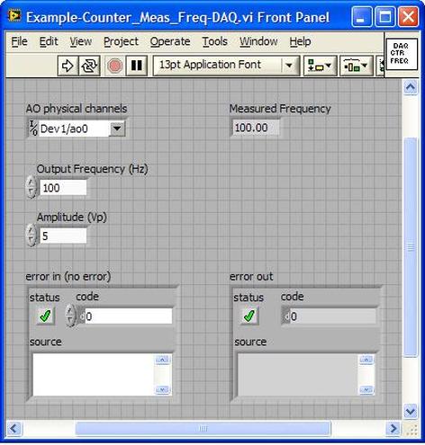 Figure 4. Measure frequency with DAQ counter front panel.
You can see in Figure 4 that the analog output frequency was programmed to 100 Hz and 100 Hz was measured with the counter. Summary This article showed some examples of using the NI PXIe 6259 M-Series DAQ. In addition to analog inputs and outputs the DAQ includes multiple digital I/O lines that could be used in a number of flexible ways. The counter is an additional useful instrument included with the DAQ. The DAQ is marketed as the all-purpose instrument and that’s what makes it interesting to work with. A DAQ can replace a number of more specialized PXI instruments like DMMs and function generators or it could be used to implement very specific high level cards like boundary scan controllers. |
Archives
December 2022
Categories
All

|
 RSS Feed