IntroductionOver the last year or so I’ve been working with NI TestStand quite a bit. While, I’ve worked with LabVIEW for several years, I have not had much exposure to TestStand. I’m hoping to write a blog series on TestStand to aid in my learning. When I started using TestStand my first question was, “how do I use this to make the creation of a test system faster?” I wanted to use LabVIEW and get a test system up and running quickly but I didn’t have any test executive infrastructure in place. That is I just wanted the operator interface, test sequencer, and report generation done so I could focus on tests. Well, that’s what TestStand is supposed to do and I was going to figure out how to make it do it. Unfortunately, I didn’t know much about TestStand and I had to figure out how to do all the basic stuff. NI always has lots of training materials available, but I just wanted to know how to get something super simple going, and I couldn’t quite find the help I wanted. If you start with an empty sequence file it looks like Figure 1. 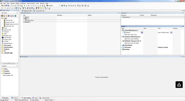 Figure 1. Empty TestStand sequence Navigating the TestStand Sequence EditorOn the left is the Insertion Palette, note in Figure 2 I’ve pointed out the Module Adaptor selection area. I have mine set to LabVIEW as I want to call my labview code on each test step. Other choices are C/C++ dll or .NET. Simply click on these to change the adaptor. There’s lots of other useful stuff in the Insertion Palette I’ll talk about later. 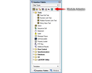 Figure 2. Module Adaptors on the Insertion Palette Another area of interest is the Steps Pane. That’s right in the middle and controls your test steps and test flow. Figure 3 shows the Steps Pane. I think the Steps Pane is technically held in the Sequence File Window. I don’t know, these terms aren’t that important. 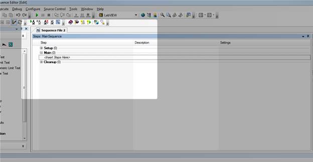 Figure 3. Steps Pane of the Sequence Editor. Off to the right is the Sequence Pane and the Variables Pane. Figure 4 shows the variables pane. 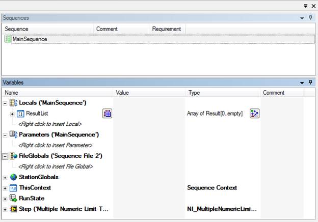 Figure 4. Variables Pane of the Sequence Editor. You’ll see that dealing with all these panes and windows can get to be a pain (I’m so funny). There are a lot of ways to move and dock all these windows. You can even pull some of them out of the sequence editor onto the Windows desktop on another monitor. So play around with it. Using a Test AdaptorNow let’s say we have some LabVIEW code and we want to run it in TestStand. Based on the code, we will pick one of the standard LabVIEW test adaptors. In this case I’ll chose Multiple Numeric Limit Test since my VI has multiple outputs that I want to evaluate with a limit and it’s probably the most useful one. In Figure 5 I dragged the Multiple Numeric Limit Test from the Insertion Palette to the Steps Pane under the Main section. 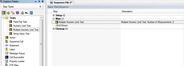 Figure 5. Use of the Multiple Numeric Limit Test adapter. Clicking on the new Multiple Numeric Limit Test, we can see in Figure 6 that the Step Setting pane is now populated with several tabs and settings options. I’m going to click on the Module tab and browse for the VI I want to run. 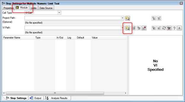 Figure 6. Selecting a module for the Multiple Numeric Limit Test adapter. The VI I am loading is just a simple sinewave generator I wrote up quick in LabVIEW. Its outputs are the sinewave amplitude and frequency. I’m going to pretend that this is my test data. See Figure 7. 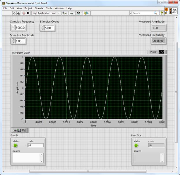 Figure 7. Front panel of sine wave measurement VI that will be used in the sequence. Now that the VI is loaded into the test sequence let’s setup TestStand to run the VI and apply limits to the measurement results. There are multiple ways to do this, the first way I know is to use the built-in results collection of TestStand. Start on the Limits tab shown in Figure 8, and use the plus sign to add two measurements. Change their names to “Amplitude” and “Frequency” or whatever makes sense. 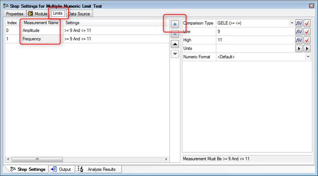 Figure 8. Applying limits to the amplitude and frequency outputs of the test VI. Next go to the Module tab shown in Figure 9 and click on the Expression Browser button in the Measured Amplitude parameter row. 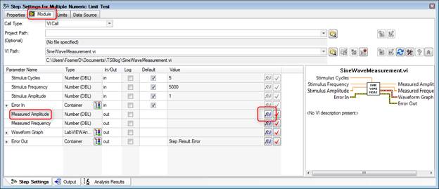 Figure 9. Accessing the Expression Browser for the amplitude output of the test VI. Once you click on the Expression Browser button you’ll see the Expression Browser dialog box shown in Figure 10. What we are trying to do is map the output of our VI to the result collection measurement name we created when we added the amplitude and frequency limits. Browse into Step -> Result -> Measurement -> [“Amplitude”] ([0]) -> Data and then click on Insert and OK. 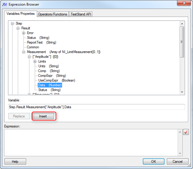 Figure 10. Connect the amplitude output from the test VI to the sequence file to be used in the limit evaluation. Go to the Data Source tab as shown in Figure 11 and click the check box called Specify Data Source for Each Measurement. Under Data Source there are two lines one for the amplitude and one for the frequency measurement. Here we are connecting our data from the TestStand results collection to the limits to be evaluated. Figure 12 shows how to use the expression browser to create the statements shown in Figure 11. 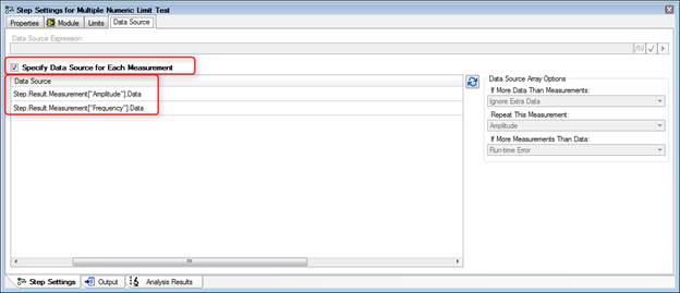 Figure 11. Connect the data source to the test step to be evaluated as limits. 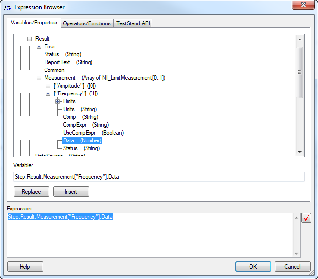 Figure 12. Using the Expression Browser to create the data source statements. Now go back to the Limits tab shown in Figure 13 and set the limit span. In my VI, the default amplitude is 1 and the frequency is 5000. As you can see there are several options for one or two sided limits, inclusive and so on. I chose GELE and selected the units. 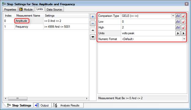 Figure 13. Options to set the limits amplitude limits, comparison type, low, high, units and numeric format. Returning to the Steps Pane, name the step something like “Sine Amplitude and Frequency.” Also, drag a label from the Insertion Palette as a way of documenting this step. The Label step type is shown in Figure 14. 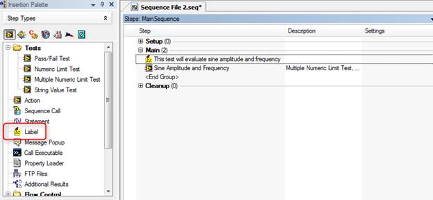 Execute the SequenceWe are actually pretty close to a complete test system at this point. It might not test much but we can now enter a DUT serial number, execute the sequence and get a report. In the Sequence Editor, click Execute-> Test UUTs, the UUT Information dialog box in Figure 15 will appear to enter a serial number for the part. Also, if you have a UBS bar-code scanner attached to the system it will automatically accept the input into this dialog box field. I didn’t know this, but a USB bar-code scanner will read text into most software, it’s just like a keyboard or mouse. You can even scan right into Excel. 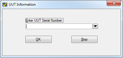 Figure 15. The UUT Information dialog box built into TestStand Type something in there like “1234” and click OK. TestStand will execute will show that the test sequence passed. The little dialog box that pops up that says “Test Sequence Passed” is shown in Figure 16, this dialog is controlled and created by the process model (so is the UUT Information, for that matter). 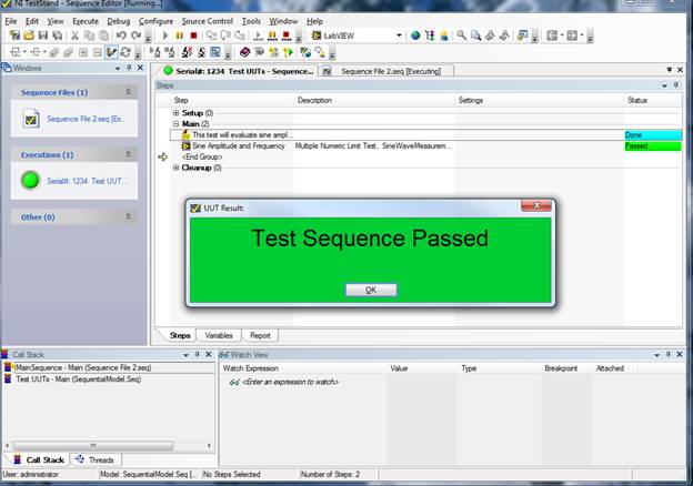 Figure 16. UUT Result dialog box shown after test run pass. Click OK on the UUT Result dialog and click Stop on the UUT Information dialog box. The test report will pop-up and you can see all the information and measurements that are collected. It’s a pretty good report right out of the box. Figure 17 shows an example of the report. 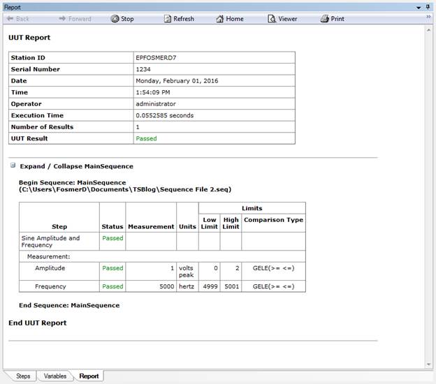 Figure 17. Example of the default sequence report created by TestStand Each time the test is executed the report will be saved in xml format to the directory in which your sequence file is saved. One last step to creating a fully functional test system is adding a user interface. The TestStand sequence editor allows you to run the sequence and your test, but it’s not setup to do real testing by a test operator. TestStand comes with premade test system user interfaces to solve just this problem. Before we look at the user interface we have to create a user with limited permissions to be our operator. In the sequence editor click View -> User Manager. Under the Users section right click and add a user called TestOperator. Right click this new user and select Properties, and click Operator. See Figure 18. 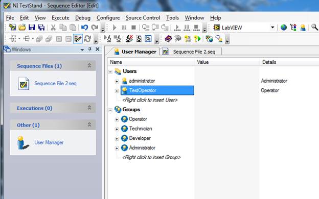 Figure 18. Creating a Test operator user profile in the TestStand user manager. Save the new user setting and close the User Manager. Note that the User Manager changes are a station setting and live with the installation of TestStand on the computer you are using, and are not saved into the sequence file. Go to this path C:\Users\Public\Documents\National Instruments\TestStand 2014 (32-bit)\UserInterfaces and you will find two folders, Simple and Full Featured. In these folders you’ll find the premade user interfaces in a variety of languages. If we go in Full Featured and LabVIEW you’ll find a file called “TestStand 2014 (32-bit) LabVIEW UI – Operator” this is the LabVIEW implementation of the user interface. From this interface you can then load your test sequence file and run it in a production environment. As shown in Figure 19, open the file and login as the new user TestOperator, then open the sequence file that we built and you are ready to test by clicking the Test UUTs button shown in Figure 20. 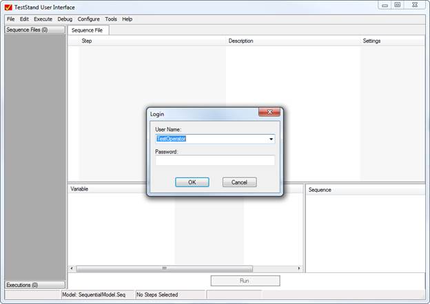 Figure 19. The TestOperator login in now available. 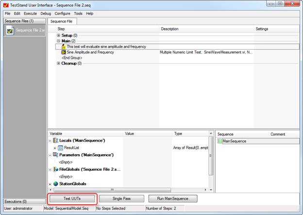 Figure 20. Begin testing by pressing the Test UUTs button. SummaryTestStand is a great tool to building a simple test system quickly as it handles a lot of the infrastructure for you like, user interface and reporting. This was the super basic stuff to load a LabVIEW VI and run it in the TestStand sequencer. TestStand can sort-of be as sophisticated and complex as you want it to be as you become more of a power user. I’m still a beginner, but I will keep writing as I learn and hopefully it will be a benefit to some others and I’ll remember how to do stuff the next time. Related
1 Comment
baalouch hatem
6/18/2021 06:22:56 am
merci de me donner le maximum des documents Your comment will be posted after it is approved.
Leave a Reply. |
Archives
December 2022
Categories
All

|
 RSS Feed