|
IQ Signals I’ve been recently reading a few journal articles about RF testing (see here) and since I don’t know much about RF or communication, I’ve been reading about some of the basics. Here is what I’ve learned about IQ signals. IQ signals or IQ data are used in RF modulation circuits. When modulating a signal you are basically taking a sine wave signal and altering the amplitude, frequency or phase in order to encode information. It turns out that building a circuit to control phase precisely is difficult, but controlling amplitude is easier. Using an IQ signal you can change the amplitude of two separate signals to control the phase, frequency and amplitude of another signal. The two signals are the I and Q (I for In-phase and Q for quadrature or 90 out of phase). A sine wave represented in a polar coordinate plane looks like this: 
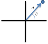
Figure 1. Sine wave represented with a polar coordinate system Converting from polar to rectangular coordinates the real and imaginary portions of the vector become the I and Q signals. Like this: 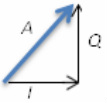
Figure 2. I and Q signals are the real and imaginary components of the rectangular coordinate system representation of a sine wave. So, I think it’s easy to see from Figure 2 that changing the amplitude of the I and Q signals can modify the amplitude, phase and frequency of the sine wave in the polar coordinate system. A typical IQ modulation circuit looks like this: 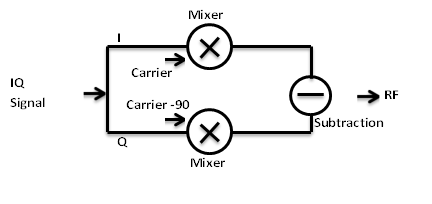
Figure 3. Circuit to implement IQ modulation
You can see in Figure 3 how the I and Q data signals are mixed with the carrier signal and subtracted to create the RF modulated signal. The subtraction is part of the mathematical conversion from rectangular to polar form. I pretty much learned all this from one place, a white paper that NI put out (here). They seem to have a number of good articles about basic RF information and RF measurement information. As usual, I’m a big fan of NI.
0 Comments
Leave a Reply. |
 RSS Feed